


USE ADDITIONAL LENS OR OPTICAL BOOSTER TO INCREASE DETECTION DISTANCE
The aim of this technical note is to present the optical solutions offered by OPTEL-TEXYS to increase detection distance. Examples from customer projects will be used to illustrate the different scenarios.
First of all, we need to explain the distinction we make between lenses and optical boosters.
The formers are used when the beam leaving the optical probe needs to be focused while maintaining fine detection resolution (< 5 mm).
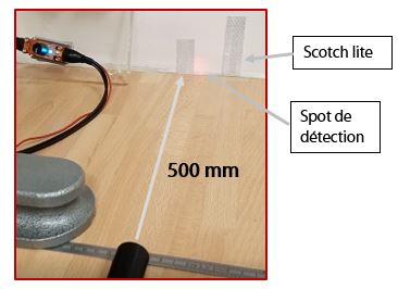
The latter can be used to greatly increase the working distance, up to 500 mm. Elements to be detected must have a highly reflective surface, such as scotch lite. Resolution is not of prime importance, and a few tops per revolution are all that's needed for measurement.
Among the reasons why our customers increase the distance between the probe and the target, the main one is to avoid a possible collision that could damage the rotating part or the probe. In some applications, the probe must be kept away from an area where the temperature exceeds specification limits (> 200°C).
Additionnal Lenses:
When adding a lens to OPTEL-TEXYS probes, it is important to define the following elements:
- The desired detection distance, in order to determine the positioning of the lens in relation to the probe tip
- The choice of probe in relation to detection distance and mark size
- Whether or not to integrate the lens into the probe during manufacture. The need for a multi-purpose probe or the testing environment will help guide you towards the right solution.
Applications:
- Multi-top speed measurement on parts, depending on brand and part size
- Encoder test patterns
- Turbo or turbine blades
2 types of probes: integrated lens or removable, manually adjustable lens
 |
 |
| MULTI YO/SLIT YO 2M D8 OPTIC | MULTI YO M3 + Additional lens |
- Advantages:
• Integrated fixed Lens into Diameter 8mm (D8 Optic)
• Adjustable: under specification
• Lens manually adjustable: “Additional lens“
• Keep a focused or parallel spot for torsional vibration
• Increase the distance
• Use with reflective zebra tapes
- Limits:
• Limited to a certain range around the nominal distance
• Example : 15 mm +/- 3 mm
Examples of probes produced for customers and used on encoder test patterns
* Probe for automotive engine test bench: SLIT YO HM8 threaded tip and integrated lens
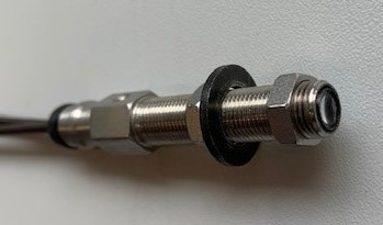
* SLIT YO probe integrated into a smooth M8 tip
Detection on a 1 mm wide mark; increased distance: from 3 to 9 mm.
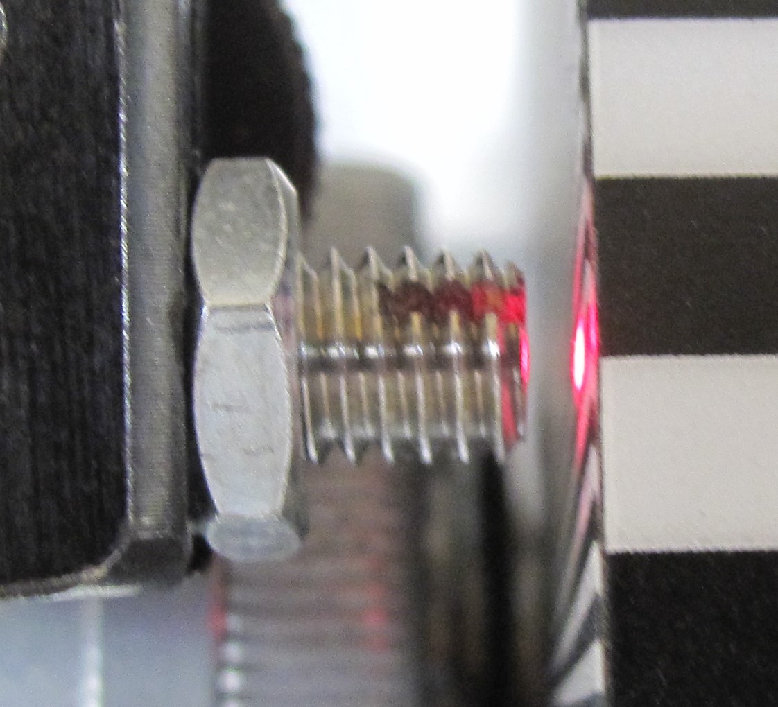
Without lens With lens
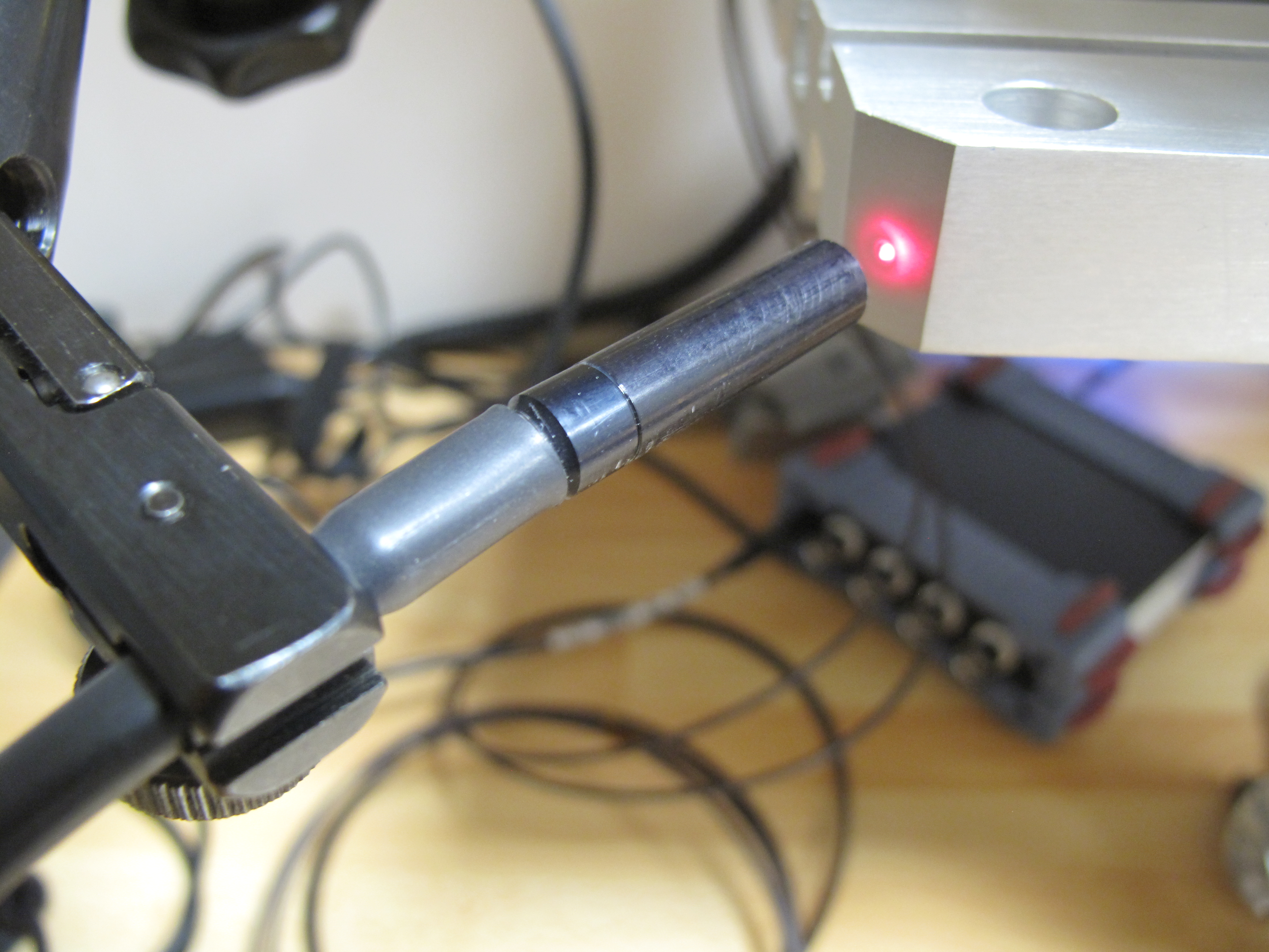
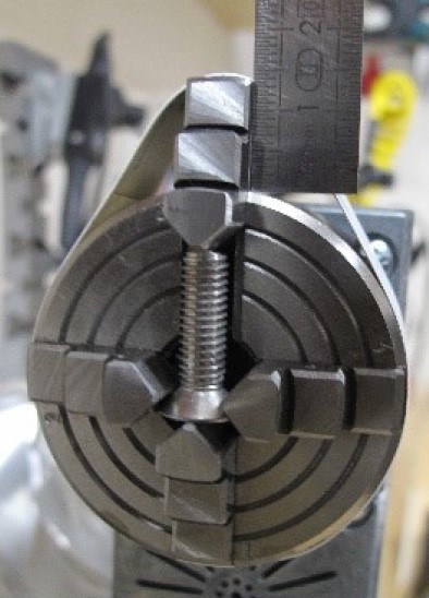
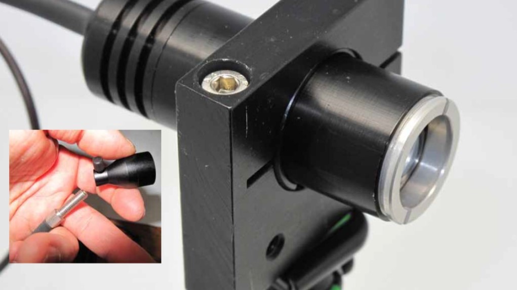
Example of a probe used for detection on turbocharger blades
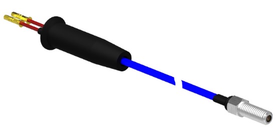
* Removable lens screwed onto YO probe with M3 tip
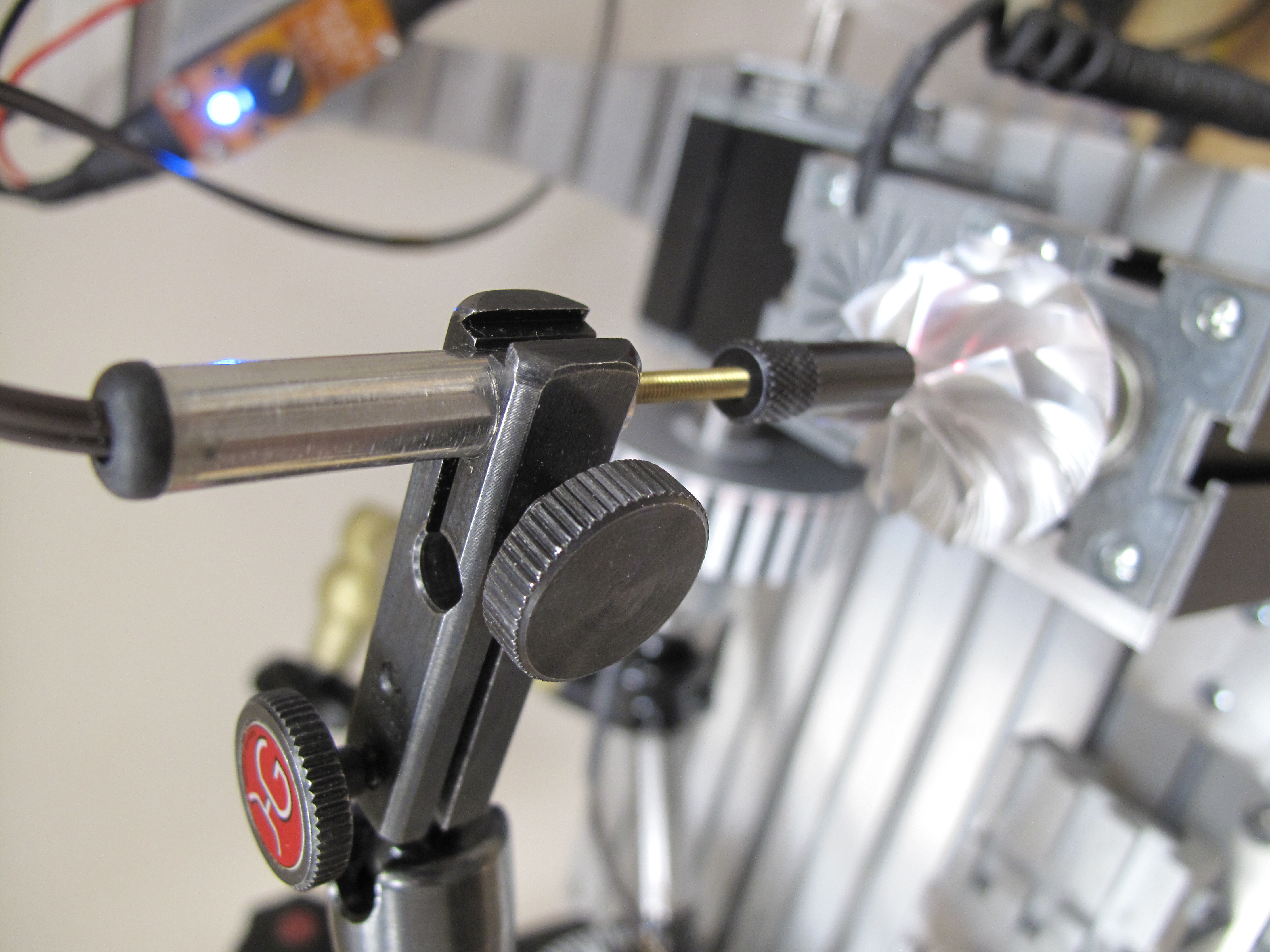
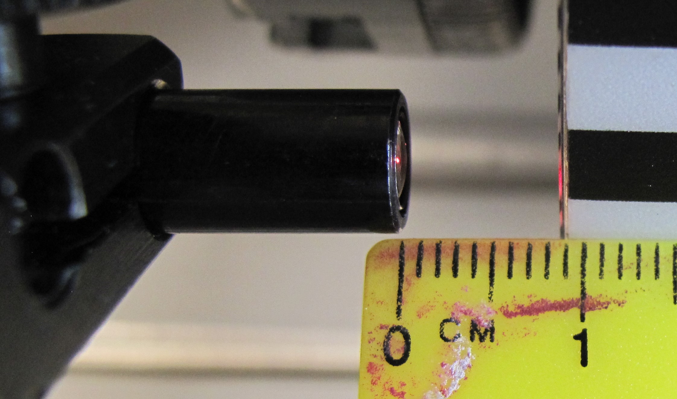
Static distance or dynamic displacement measurement is a particular application of the 152 M sensor and its analogue output.
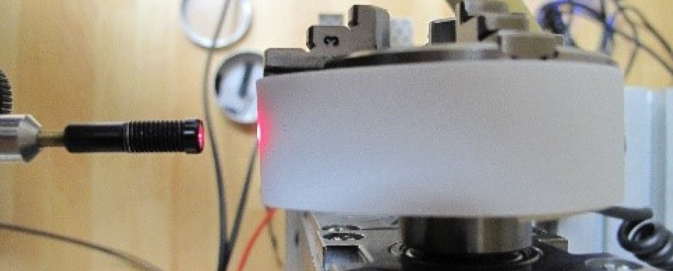
In the example below, an additional lens is used to move the probe away from the white reflective strip. This covers a measurement range of 14 mm, giving a final working range of between 9 and 23mm.
N.B.: Measurement accuracy has not been analysed. It requires calibration.
Assembly: cam prototype with white band
Sensor output signal (potentiometer position at maximum): 14 mm ~3.6 V
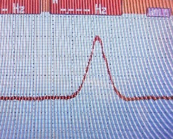
Sensor installation: lens 9 mm from cam
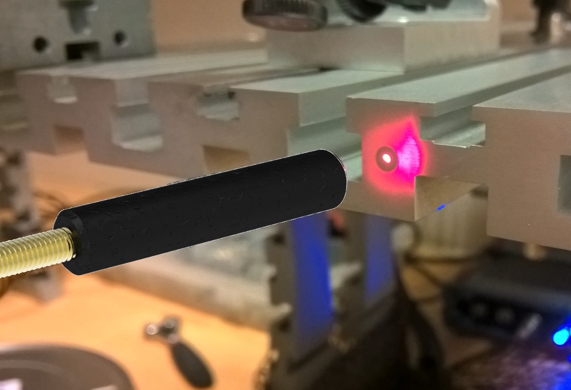
Optical Booster
The main application is the detection of a top lap on Scotch lite for an average or instantaneous speed measurement. A few tops are possible if the size of the target allows, as Scotch Lite is 25.4 mm wide.
The 1st solution has an integrated lens.
This is adjusted according to the "detection distance" specification given by the customer. Easy to fit with an M8 diameter end cap, the maximum detection distance is around 150 mm.
Its use is limited to ambient temperatures of 85°C maximum.
2nd solution: the booster is added to a probe with an HM6 tip
It increases the distance to 500 mm. As before, it is limited to a few tops per turn with detection on a highly reflective surface such as Scotch Lite
Conclusion
For optimum use of Optel-Texys sensors, we recommend positioning the probe at a working distance of between 1 and 10 mm.
This avoids detection problems, which can be explained by Descartes' law. If the orientation of your part changes during rotation, the reflected light is reflected at a greater angle than the incident light.
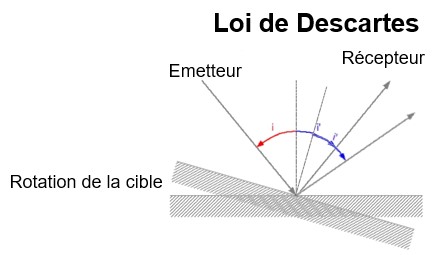
Two problems may arise:
- Loss of all or part of the signal, making speed measurement impossible or erroneous
- A variation in the signal leading to an abnormal increase in the 1st harmonic and requiring specific signal processing, which can have an impact on the analysis.
However, if your test conditions require the probe to be located further away, we can work with you to define the solution best suited to your application.
Another parameter to take into account is increased light absorption when using lenses or boosters. It may be preferable to use sensors with fairly powerful emissions, such as the 152 G8 and 152M.
For more details on our technology and the use of sensors with fibre-optic probes, you can also contact us directly using the form on the website www.optel-texys.com