


DREHZAHLSENSOREN FÜR DIE ANALYSE VON DREHSCHWINGUNGEN
Through different work and research made in the Universities of FERRARA and BOLOGNA from which this article is an extract, OPTEL-TEXYS highlights the contribution of its optical speed sensors in the frame of testing and simulation when the goal is to analyse the torsional vibration of a rotating machine in order to solve NVH issues.
The subject is introduced by an example of a work done on a vibratory feeder for pasta and is developed with measurements made on a test rig equipped with combustion engine, brake and transmission shaft with a flexible coupling.
1. Introduction
Vibratory feeders are employed over a wide range of applications, like the motion of pasta during the pre-drying process for example. Regarding high performance vibratory feeders, great levels of noise and vibration are expected due to the high working speed and the huge inertia forces involved. Such levels of noise and vibration have to be controlled since they produce malfunctioning and unhealthy work environment due to loudness and vibrations transmitted to the ground. To investigate the issue of this mechanical system and propose solutions of improvement, the study has been deployed through numerical and experimental approach.
The mechanical system under investigations is composed by three horizontal parallel frames. The upper frame and the lower frame are rigidly joined and connected to the structural base by means of leaf springs. The oscillation motion is achieved by an eccentric-and-rod mechanism driven by an induction motor. The single degree of freedom model has been validated with experimental measurements in different operational conditions. The results of simulations and experimental measurements have allowed the identifications of the main causes of the abnormal vibro-acoustic behaviour of the feeder.
Several experimental measurements have been carried out in order to identify the vibration sources of the system: operational acceleration measurements, measure of the torsional vibration and modal analysis. Concerning the operational vibration measurements, the signals have been acquired by the means of three miniature piezoelectric accelerometers.
Torsional vibration measurements on the shaft were carried out by using an optical sensor (OPTEL-TEXYS 152 G7) and an optical fibre probe (OPTEL-TEXYS MULTI YO), acquiring TTL signals from zebra tapes (OPTEL-TEXYS MR2) with line width of 2 mm. The probe was fixed to the structural base with a stiff bracket whereas the zebra tape was mounted on the shaft as depicted in the figure. This setup provides the instantaneous angular speed of the shaft (Figure 1).
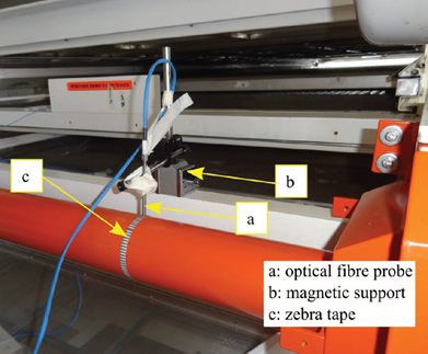
Figure 1: Set up of the optical fibre probe and the zebra tape
The simulation results and the experimental measurements highlight abnormal vibration level of the vibratory feeder at the working speed of 360 rpm. The excitation of some natural frequencies of the frames at the working speed contributes to the high vibration level of the feeder. The results of the torsional oscillation measurements are depicted in Figure 2. The upper diagrams of Figure 3 highlights that at the nominal speed of 300 rpm the speed variation is lower than the speed variation at 360 rpm (lower diagrams). Therefore, the measurement of the torsional oscillation highlighted a huge speed variation due to the irregularity of the motion, which can lead to malfunctioning.
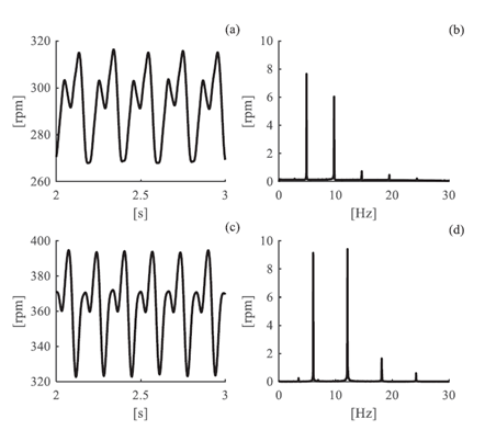
Figure 2: Instantaneous speed in time and frequency domains at 300 rpm (a-b) and at 360 rpm (c-d)
2. Application in automotive industry
>This work addresses the dynamic analysis of the coupling components in internal combustion engine test rigs from the experimental standpoint. In the current set up, the output shaft of the engine transmission is connected with an electromechanical brake by means of a transmission shaft which hosts a torsional coupling with rubber elements (high flexible couplings). Recently, the rising performance of engines has led to an abrupt increase of the dynamic loads affecting the driveline, particularly the elastic couplings. A negative effect has been affecting the mentioned torsional coupling, with high oscillations of its components leading to the collapse of the rubber elements.
An experimental campaign was thus carried out, with the aim of characterizing the current system dynamic behaviour, determining the response signature, and detecting the source of critical problems, and finding possible modifications able to solve the problem, with a low impact into the cell architecture. In particular, torsional vibration measurements have been achieved by a coder-based technique using: optical sensors (OPTEL-TEXYS 152 G7 RV4), acquiring TTL signals from zebra tapes with line width of 2 mm mounted like the sensors before and after the coupling rubber elements, at the engine-side and brake-side, respectively, in order to track the torsional oscillations affecting the rubber element. It provides Instantaneous angular speed (IAS) measurements conventionally denoted as nbs and nes respectively.
The test rig consists of a few main components: the crankshaft by means of a gearing with a constant and few gear ratio of about 3; the transmission shaft is connected to the electromagnetic brake by the means of the flexible coupling. This one is composed of two rubber elements, working in series and clumped to three metallic flanges (Figure 3).
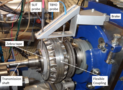
Figure 3: Test rig and optical sensor set up
The high number of lines per revolution (94 and 78, for the brake-side and engine-side respectively) guaranteed a suitable resolution in the torsional measurements. In addition, the tacho signal from a phonic wheel with 8 teeth fixed to the engine crankshaft was acquired; and for enforcing the data analysis, a tri-axial accelerometer was glued to the engine block support. The counting rate of the optical sensors was 800 MHz and the sampling frequency of the others channels was 10240 Hz.
Test procedure and data processing
The system was tested at different operational conditions, namely runups and stationary regimes, and for different working conditions in terms of velocity and throttle opening. Runups were conducted in order to find out resonant bandwidths of the system for a continuous change of engine speed. In addition, stationary tests were performed to have more precise information about the natural frequencies for a number of different constant regimes. Two tests campaigns were performed, corresponding to rubber elements of the flexible coupling having different hardness (45 and 70 Sh).
The torsional oscillations of the two coupling ends were evaluated in terms of their relative velocity, denoted as nrel and determined as nrel = nes – nbs. The data of runup tests were analysed in the Time and Time-Frequency domains, whereas data measured for stationary tests were analysed in the Time, Frequency and Order domains.
Results
Among all collected data, only the results of tests with the with “45 Sh” flexible coupling is reported in the present article to highlight the measurements and analyses done by the means of the OPTEL-TEXYS tachometers. In this section, only the runup performed with the lowest acceleration are shown.
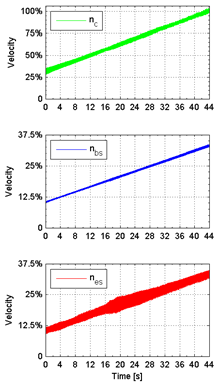
Figure 4: Time data of velocity signalFigure 4: Time data of velocity signals
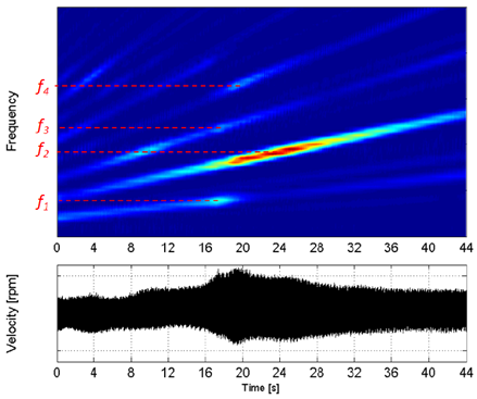
Figure 5: Time-Frequency analysis of the relative velocity
In Figure 4, the time series of the acquired IAS are plotted as scaled to the maximum value of the crankshaft velocity nc. The oscillation of the velocity nes of the engine-side flange of the coupling as significantly higher and more irregular than the brake-side one (nbs). In particular, it is subjected to a very high increment after the sixteenth second of the run.
The analysis of this oscillation is the main tool to understand the dynamic phenomenon underlying the system behaviour. To this aim the analysis was focused on the relative velocity between the two coupling ends, , which was analysed in the Time-Frequency domain to highlight the presence of resonant bands of the system. In Figure 5, it an be noted that the frequency content of nrel is dominated by order 1 of the crankshaft rotation and – to a smaller extent – by order 0.5, 1.5, and 2, being order 0.5 associated with the engine thermodynamic cycle. Starting from the sixteenth second of the runup, the amplitude of nrel significantly increases with a frequency content firstly associated with the crankshaft order 0.5 (16-18 s) and then dominated by order 1 for a long-time interval (18-30 s). Two natural frequencies, f1 and f2, are excited in these two phases, being f2 widespread in a large bandwidth. It could be noted that the second one is excited also by the crankshaft order 1.5, with lower energy, in the interval 8-12 s. Other possible higher resonances, f3 and f4, are slightly excited by the crankshaft orders 1.5 and 2 at about 18-20 s, but with a low energy.
Concerning stationary tests and measurements made with the 70 Sh flexible coupling, the analysis is developed in the original paper. During the investigation on the driveline of a test rig for internal combustion engines, from the experimental point of view, the focus was placed on the torsional vibrations of the flexible coupling that was supposed to be the cause of the frequent early collapse of its rubber elements.
The performed campaigns permitted to quantify the torsional oscillations (measured in terms of relative velocity between two ends) and to identify the mains resonances dominating the system dynamic response. In particular, one of the natural frequencies (f2), widespread in a pretty large bandwidth, could ne excited for many engine regimes and was thus defined as the main target of possible interventions to modify the coupling elastodynamic properties.
Conclusion / In sight
These two different examples show how simulation and/or measurement have been used for acquiring data, analysing them through different methods and finding solution for reducing noise and vibration issues. But the interesting point is the proposal of a measurement approach where speed sensors can be added to others or can be the major sensors used for detecting speed oscillation. Thus, the post-processing and the analyse of the velocity with accurate and non-invasive sensors could lead to measure torsional vibration and understand phenomenon in rotating machines like acyclism.
Furthermore, engineers in NVH department could find more application of these speed sensors by considering other kind of analysis methods. Let’s think of what could have been done in the test rig above where relative velocity has been measured and could have been turned into static and dynamic torque.
References
- Improvement of the vibro-acoustic behaviour of vibratory feeders for pasta by modelling and experimental techniques; Marco BUZZONI, Emiliano MUCCHI, Giorgio DALPIAZ; In Proceedings of the INTER-NOISE 2017- 46th International Congress and Exposition on Noise Control Engineering, Volume 2017-January, 2017
- Torsional Vibration Analysis of a Test Rig Driveline Equipped with a Flexible Coupling; Marco TRONCOSSI, University of Bologna; Emiliano MUCCHI, University of Ferrara; Alessandro RIVOLA, In Recent advances in mechanical engineering - ISBN:9789604744022, 2014